8-Channel Sensor Input Temperature Transmitter

- Microcyber
- China
- In Stock
- 500 Sets/Month
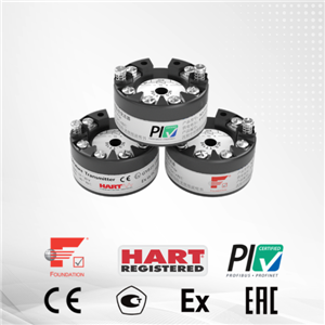
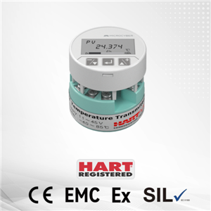
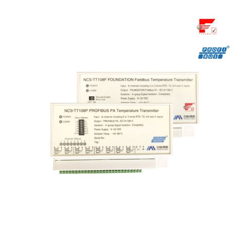
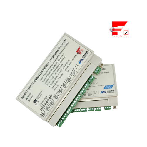
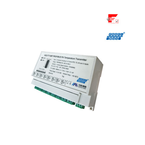
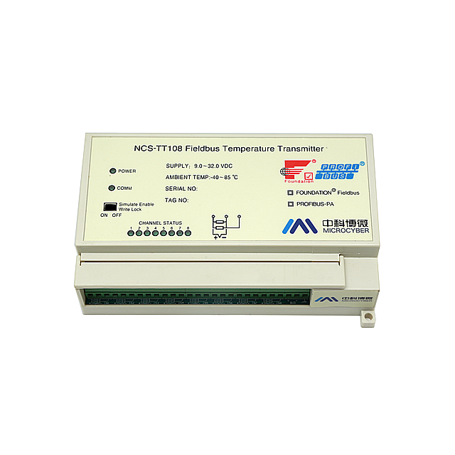
NCS-TT108F/P temperature transmitter
1.Dual channel 4 types of thermal resistance and 8 types of thermocouple
2.Thermal resistance supports 2-wire and 3-wire
3.Cold junction compensation accuracy of voltage signal can reach ±1.0℃
4.High precision ( grade 0.1), low temperature drift ( ±50ppm/℃)
5. FF: FCG (FF ITK6) interoperability test, intrinsically safe, explosion-proof certification
6. PA: conform to PROFIBUS PA version 3.02
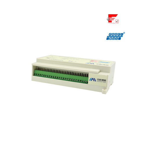
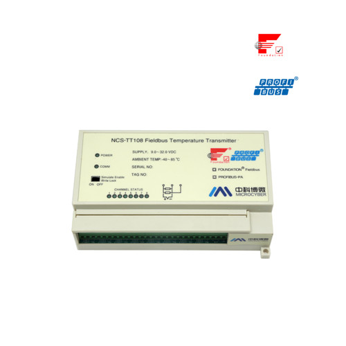
8-Channel Sensor Input Temperature Transmitter: NCS-TT108 smart temperature transmitter adopt PVC fire-retardant plastic shell, which can be installed in the control room. When it is required to be installed outdoors.outdoor Aluminum box, with a water-proof body and die-cast aluminum materials, must be selected.
NCS-TT108 digital temperature transmitter uses digital technology. It has simple interface between field and control room, which reduces the expense of installation, operation and maintenance.
Hart Temperature Transmitter Features:
Support many types of thermal resistance and thermocouple sensors
Thermal resistance supports 2/3-wire connection mode
Thermocouple can use cold end compensation function
Temperature Sensor Parameters:
Input Signal: Resistance: PT100, CU50, CU100, 0~500Ω, 0~4000Ω
Thermocouple: B, E, J, N, K, R, S, T
Voltage signal: -100mV~100mV
Channel: 8-channel
RTD Wiring: 2-wire, 3-wire,
Bus Power: 9~32 VDC Current Consumption (Static): ≤20mA
Bus Signal: Communication Ratio 31.25Kbit/s, Current Mode
Isolation: Between Input Channel And Bus: 500Vrms (707 VDC)
Between Temperature Converter Module: 500Vrms (707 VDC)
The Two Temperature Input Channels in the Module are Not Isolated.
Working Temperature: -40℃~85℃
Humidity Range: 0%~100%RH
Start Time: ≤5s
Refresh Time: 0.2s
Protection: IP20; Outside Box IP67
Vibration: Arbitrary axial 0~200Hz, Error is±0.05%/g of Largest Range
EMC: Bus Terminal: GB/T 18268-2000 Table A1
Sensor Terminal: GB/T 18268-2000 Table 1
RTD Technical Parameter :
RTD Accuracy Parameter at Normal Temperature (25℃)
Signal Type | Suggested Range (℃) | Accuracy |
Resistance Signal | 0~500Ω,0~4000Ω | ±0.05% |
PT100 | -200 ~ 850℃ | ±0.2℃ |
PT1000 | -200 ~ 850℃ | ±0.1℃ |
CU50 | -50 ~ 150℃ | ±0.3℃ |
CU100 | -50~ 150℃ | ±0.2℃ |
RTD Other Parameter:
Wiring | 2, 3 |
Data Refresh Ratio | ≥ 1Hz/each channel |
Common Mode Rejection | ≥80Db (50Hz) |
Series Mode Rejection | ≥60dB(50Hz) |
Temperature Drift | ±0.001/℃ |
Hermocouple Parameter:
Thermocouple Accuracy Parameter at Normal Temperature (25℃)
Signal Type | Suggested Range (℃) | Accuracy |
mV | -100 mV ~100mV | 0.05% |
B | 500℃~1810℃ | ±1.0℃ |
E | -200℃~1000℃ | ±0.6℃ |
J | -190℃~1300℃ | ±0.8℃ |
K | -200℃~1372℃ | ±0.8℃ |
N | -190℃~1300℃ | ±1.0℃ |
R | 0℃~1768℃ | ±1.0℃ |
S | 0℃~1768℃ | ±1.0℃ |
T | -200℃~400℃ | ±0.6℃ |
Thermocouple Other Parameter:
Compensation Accuracy | < ±1℃ |
Data Refresh Ratio | ≥ 1Hz |
Sensor Type | B,E,J,N,K,R,S,T -100mV~100mV Voltage |
Common Mode Rejection | ≥60Db (50Hz) |
Series Mode Rejection | ≥60dB(50Hz) |
Temperature Drift | ±0.001/℃ |
Temperature Sensor Physical Parameter:
Material: Flame retardant plastic;Die-casting aluminum (outside box)
Protection: IP20; Outside box IP67
Weight: 0.42kg 1.98kg (With outside box)
Temperature Sensor Dimension:
Dimensions are shown as the following:

Temperature Sensor Dimension(mm)
Temperature Sensor Structure:

1 | PVC film | 2 | Block board | 3 | Roof cover | 4 | Communication board |
5 | Tightening screw | 6 | PVC label | 7 | Pin | 8 | Instrument board |
9 | Rail guide lock | 10 | Bottom cover |
Temperature Transducer Installation
Mount of Transmitter


Mount of guide rail Mount of screw
When thetemperature transmitter needs mounting in outdoor, it must be mounted in outdoor box, whose case material is die-casting aluminum, and cable seal point is copper chroming.


Outdoor case Mounted in outdoor box
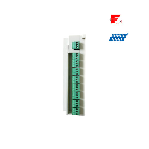
Connection:
NCS-TT108 Temperature transmitter'spower and bus signal share one couple cable, called bus cable. Customer is advised to use dedicated cable especially for fieldbus, recommended by IEC61158-2. The bus connection terminal of this temperature transmitter is positioned at the very right of connection terminals. From left to right, they are ‘bus+’, ‘bus-’and ‘earth’, as showed in the following figure.
Of the left terminals of sensor's signal connection terminal strip, every three terminals in sequence form one channel’s connection terminal, and will connect channel one to channel eight sensors, from left to right in sequence. The detailed connection mode is showed as following figure.

Temperature transmitter connection
Signal cable and bus cable shall not share wiring tube or open wire trunking with other device and shall be far away from high-power device.

Temperature transmitter Cable sealing connector
There are nine cable sealing connectors for outdoor box. The connector on side wall, labeled ‘Power/Signal’, should connect fieldbus cable, and cable connectors on inferior wall should connect every channel sensor to connect cable, from left to right they are channel one, channel two…channel eight in sequence.
How To Choose NCS-TT108 Smart Temperature Transmitter?


FAQ
Q: Can I get a free electronic manual?
A: Yes, if you want it, please contact us.
Q: How does NCS-TT108 Smart Temperature Transmitter work?
A: NCS-TT108 collects thermo resistance and thermocouple signal, which is converted into fieldbus signal after arithmetic and handling, and achieves temperature measurement functions.
Q: How many parts does NCS-TT108 Smart Temperature Transmitter consist of?
A: Communication board and instrument board.
Q: Can I get a free electronic manual?
A: Yes, if you want it, please contact us.
Q: Can you provided OEM service?
A: Yes, we can, such as communication board, we can also provided fieldbus development toolkit.