HART Communication Controller

- Microcyber
- China
- In Stock
- 500 Sets/Month
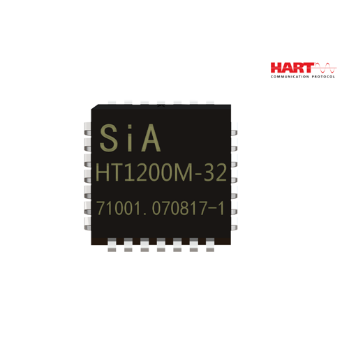
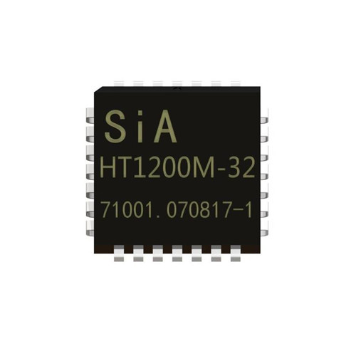
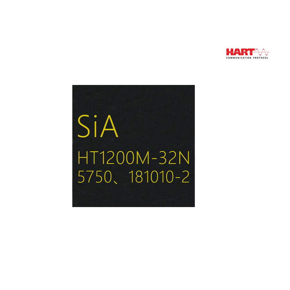
HT1200M HART Communication Controller
1. Integrated receiving the circuit of band-pass filter and transmitting signal waveform shaping
2. Single chip, FSK modem (Semi-duplex 1200bit/s)
3. External 460.8kHz crystal or ceramic filter
4. Working temperature: -40℃~85℃
5. Power supply voltage: 3.3V~5.0V
6. Working current: < 140uA (3.3V)
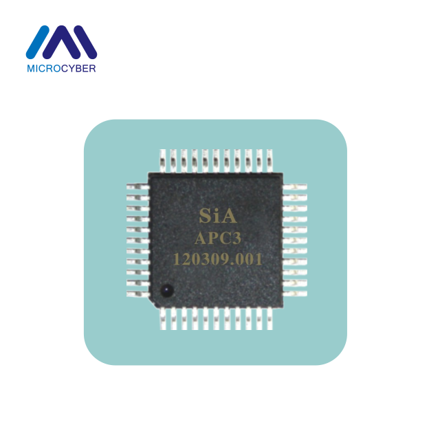
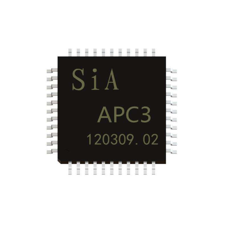
7. LQFP32 and QFN32 package
HART Communication Controller Brief Introduction
General Description
HART Communication Controller Brief Introduction .The HT1200M is a single-chip, CMOS modem for use in Highway Addressable Remote Transducer (HART) field instruments and masters. The modem and a few external passive components provide all of the functions needed to satisfy HART physical layer requirements including modulation, demodulation, receive filtering, carrier detect and transmit-signal shaping. The HT1200M is pin-compatible with the SYM20C15. See the Pin Description and Functional Description sections for details on pin compatibility with the SYM20C15.
The HT1200M uses Phase Continuous Frequency Shift Keying (FSK) at 1200 bits per second. To conserve power the receive circuits are disabled during transmit operations and vice versa. This provides the half-duplex operation used in HART communications.

Features
HART Communication Controller Brief Introduction Can be used in designs presently using the SYM20C15 or equivalent type chip
Single-chip, half-duplex 1200 bits per second FSK modem
Bell 202 shift frequencies of 1200 Hz and 2200 Hz
3.3V-5.0V power supply
Transmit-signal wave shaping
Receive band-pass filter
Low power: optimal for intrinsically safe applications CMOS compatible
Internal oscillator requires 460.8kHz crystal or ceramic resonator
Meets HART physical layer requirements
Industrial temperature range of -40 °C to +85 °C
Available in a 28-pin PLCC and 32-pin LQFP packages
Main Characteristic
HART Communication Controller Brief Introduction
Single chip
FSK modem (Semi-duplex 1200b/s)
Integrates circuit of receiving band-pass filter with circuit of sending
signal waveform and reshaping
External connection with 460.8kHz crystal or ceramic filter
Internal clock vibrator or external clock input
Operation temperature: -40℃~85℃
Voltage: 3.3V~5.0V
Operation current:<200uA
LQFP32 and PLCC28 package
Function Description
The HART Communication Controller Brief Introduction HT1200M is a functional equivalent of the SYM20C15 HART Modem. It contains a transmit data modulator and signal shaper, carrier detect circuitry, analog receiver and demodulator circuitry and an oscillator.
The internal HART modulates the transmit-signal and demodulates the receive signal. The transmit-signal shaper enables the HT1200M to transmit a HART compliant signal. The carrier is detected by comparing the receiver filter output with the difference between two external voltage references. The analog receive circuitry band-pass filters the received signal for input to the modem and the carrier detect circuitry. The oscillator provides the modem with a stable time base using either a simple external resonator or an external clock source.
HART Communication Controller Typical Application

HART Communication Controller Pin Assignment

Parameters
HART Communication Controller Brief Introduction
ABSOLUTE MAXIMUMS | ||||
Symbol | Parameter | Min. | Max. | Units |
TA | Ambient | -40 | +85 | ℃ |
TS | Storage Temperature | -55 | +150 | ℃ |
VDD | Supply Voltage | 2.7 | 5.5 | V |
VIN , VOUT | DC Input, Output | -0.3 | VDD+0.3 | V |
TL | Lead Temperature (soldering) | 250 | ℃ | |
DC CHARACTERISTICS (VDD = 2.7V to 5.5V, VSS = 0V, TA = -40C to +85C) | ||||||
Symbol | Parameter | VDD | Min. | Typical | Max. | Units |
VIL | Input Voltage, Low | 2.7-5.5V | 0.3*VDD | V | ||
VIL | INRESET、INRTS | 2.7-3.3V | 0.9 | 1.2 | 1.4 | V |
VIH | Input Voltage | 2.7-5.5V | 0.7*VDD | V | ||
VIH | INRESET、INRTS | 2.7-3.3V | 1.3 | 1.8 | 2.3 | V |
VOL | Output Voltage, Low (IOL = -1.8mA) |
2.7-3.3V |
0.4 | V | ||
VOH | Output Voltage, High (IOH = -1.8mA) |
2.7-3.3V |
VDD-1.0 | V | ||
CIN | Input Capacitance Analog Input IRXA Digital Input | 2.1 20.8 3.1 | pF | |||
IIL/IH | Input Leakage Current | ±5 | µA | |||
IOLL | Output Leakage Current | ±5 | µA | |||
IDD | Power Supply Current (RBIAS=500kΩ,IAREF=1.235V) | 3.3 5.0 | 170 200 | µA | ||
IAREF | Analog Reference | 3.3 5.0 | 1.2 | 1.235 2.5 | 2.6 | V |
ICDREF | Carrier Detect Reference (IAREF=.08V) | 1.15 | V | |||
OCBIAS | Comparator Bias Current (RBIAS=500kΩ, IAREF=1.235V) | 2.5 | µA | |||
AC CHARACTERISTICS (VDD = 2.7V to 5.5V, VSS = 0V, TA = -40C to +85C) | |||||
Pin Name | Description | Min. | Typical | Max. | Units |
IRXA | Receive Analog Input |
1190 |
1200 |
+/-150 |
nA |
Leakage Current | |||||
Frequency-Mark(Logic 1) | 1210 | Hz | |||
Frequency-Space(Logic 0) | 2180 | 2200 | 2220 | Hz | |
ORXAF | Output of the High-pass Filter Slew Rate Gain Bandwidth (GBW) Voltage Range |
150 0.15 |
0.025 |
VDD-0.15 |
V/µs kHz V/µs |
IRXAC | Carrier Detect & Receive Filter Input Leakage Current |
+/-500 |
nA | ||
OTXA | Modulator Output Frequency-Mark(Logic1) Frequency-Space(Logic0) Amplitude(IAREF1.235V) Slop Loading(IAREF=1.235V) |
30 |
1196.9 2194.3 500 2.84 |
Hz Hz mV p-p mV/µs kΩ | |
ORXD | Receive Digital Output Rise/Fall Time |
20 | ns | ||
OCD | Carrier Detect Output Rise/Fall Time |
20 | ns | ||
MODEM CHARACTERISTIC (VDD = 2.7V to 5.5V, VSS = OV, TA = -40 C to +85 C) | ||||
Parameter | Min. | Typical | Max. | Units |
Demodulater Jitter Conditions Input frequencies at 1200Hz+/-10Hz,2200Hz+/-20Hz Clock frequency of 460.8kHz+/-0.1% Input(HLXA) asymmetry,0 |
12 |
% of 1 bit | ||
CERAMIC RESONATOR - EXTERNAL CLOCK SPECIFICATIONS (VDD = 2.7V to 5.5V, VSS = OV, TA = -40 C to +85 C) | ||||
Parameter | Min. | Typical | Max. | Units |
Resonator Tolerance Frequency |
460.8 |
1% |
% kHz | |
External |
456.2 |
460.8 |
465.4 |
kHz |
Clock Frequency | ||||
Duty Cycle | 40 | 50 | 60 | % |
Amplitude | VOH-VOL | V | ||
Dimension
HART Communication Controller Brief Introduction Package Information


LQFP32


PLCC28
FAQ
Q: Can I get a free electronic manual?
A: Yes, if you want it, please contact us.
Q: How to set the analog reference voltage?
A: This analog input sets the do operating point of the operational amplifiers and comparators and is usually selected to split the do potential between VDD and Vss. IAREF in DC Characteristics refer to Electrical Characteristics.
Q: Can you provided OEM service?
A: Yes, we can, such as communication board, we can also provided fieldbus development toolkit.
Hot Products--HART Communication Controller