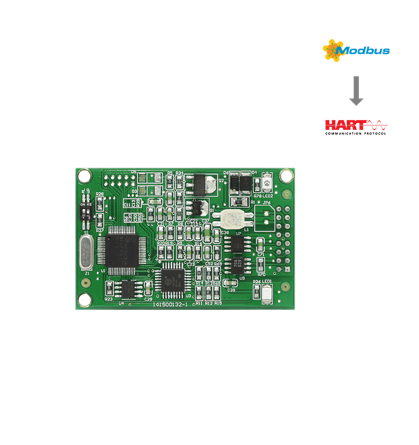
HART Module Modbus to HART Module

- Microcyber
- China
- In Stock
- 500 Sets/Month
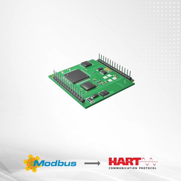
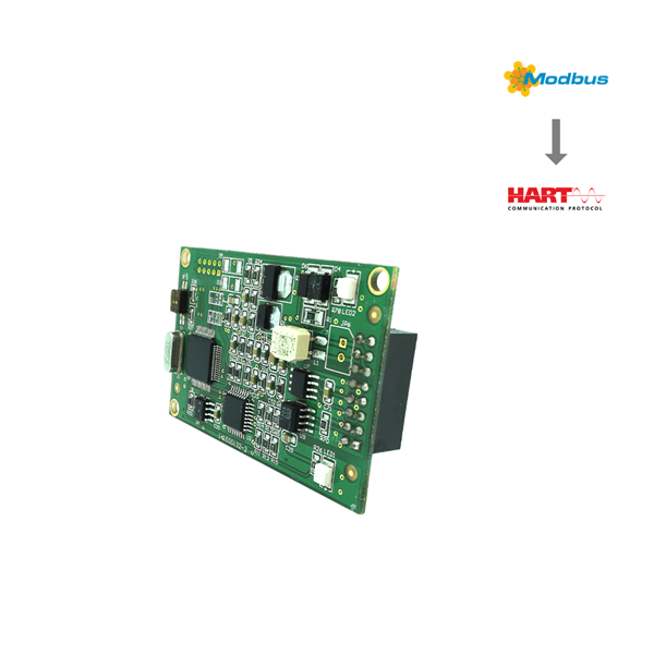
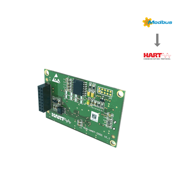
Microcyber Corporation (hereinafter referred to as “Microcyber”) has customized many built-in protocol converting modules for the majority of field device manufacturers, supporting to connect MODBUS RTU protocol (hereinafter referred to as “MODBUS” protocol) slave device into a variety of fieldbus system. The function of M0310 built-in MODBUS to HART module (hereinafter referred to as "HART module") is to convert MODBUS slave device into HART slave device.
Modbus to HART Module Features
Compliant with standard Modbus RTU protocol
provide HART communication ability to Mod bus device
Support 375/475 handheld device
Electrical interface connected with Modbus device supports TTL level, RS485 and RS232
Support HART 5/6/7 protocol
Support 6 device variables and 4 dynamic variables
Modbus to HART Module Conversion Logic
HART module can convert MODBUS flow / level instrument to HART flow / level instrument.
HART Module (M0310) is a built-in converting module, converting MODBUS input device into HART current output device. HART module is built into MODBUS input device (measure instruments, like flow, level etc.), and then MODBUS application layer protocol is run by TTL level signal. HART module as MODBUS master and HART slave, converts data registers (such as input register, holding register) of MODBUS device into all the dynamic variables of HART commands. For example, holding register of one flow meter with address 30000 (range 1-65536) contains instantaneous flow value. Then we may configure the holding register to device variable 0 (range 0-5) of HART module. And nominate device 0 as Primary variable (or Secondary, Teritary, Quatenary variable). Converting logic is shown in the figure below.

Data Mapping Logic Diagram
HART Module as a universal product will face with different interface features of various MODBUS devices (slave address, baud rate, parity, etc.), data storage mode (data register address, data type, sequence of bytes, etc.) and end users‟ requirements to HART dynamic variable allocation (data register mapping to device variable, device variable mapping to dynamic variable). All above may be configured again by device manufacturer.
Microcyber can provide PC configuration software for above configuration. Also provide HART module DD files, which is for HART master station (PC, communicator) which owns DD file analytical ability. HART module is configured through HART communication from HART master station, to confirm interface features between HART module and MODBUS device, data storage mode and mapping from device variable to HART dynamic variable.
After above configuration, HART master devie can access dynamic variable of HART module with HART commands, and realize the data‟s digital transmission from MODBUS data register (such as instaneous flow values of memory flowmeter) to HART master.
Modbus to HART ModuleAnalog Current Output
In HART module, the measuring value of Primary variable (PV) is transmitted by 4-20mA analog current output value. For example, flowmeter‟s instaneous flow is named as HART primary variable. When instanenous flow value achieves half of measuring range. HART module outputs 12.000mA.
Running HART module continuously compares primary variable value with upper and lower limit of its range. If primary variable value reaches to its upper limit, HART module outputs analog current 20.000 mA. If primary variable value down to zero, HART module outputs analog current 4.000 mA.
If primary variable value exceeds its upper and lower limit, HART module outputs a fixed current, indicating primary variable exceeds range, and the current value is called saturated output current. If primary variable value is more than upper limit, HART module outputs fixed 20.800mA; if less than lower limit, HART module outputs fixed 3.800mA.
HART module has another group of fixed current used for fault alarm, which can be selectd by a DIP switch on HART module for high or low current alarm. If selecting high current alarm, when fault found, HART module outputs 21.750 mA. If selecting low current alarm, when fault found, HART module outputs 3.750 mA.
Two Groups Fixed Output Current of HART Module
Transfinite Direction of Primary Variable (not optional): Saturated Output Current Value
Exceed lower limit: 3.800mA
Exceed upper limit: 20.800mA
Fault alarm mode (Alternative): Alarm output current value
Low current alarm: 3.750mA
High current alarm: 21.750mA
When HART module polling address isn‟t set as „0‟, no matter how much is primary variable value, HART module analog channel outputs fixed 4.000mA. Only polling address is set as „0‟, HART module outputs 4-20mA analog current corresponding to primary variable.
Configure Interface
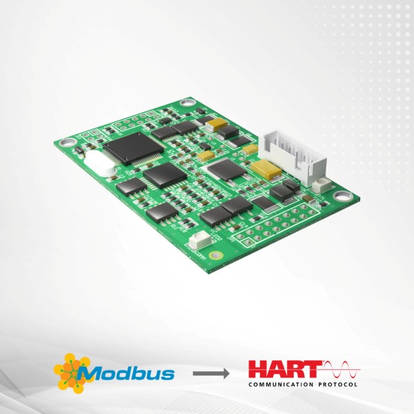
HART module is between HART bus and MODBUS device. It connects the main control board (hereinafter referred to as the "user board”) of the field device through the socket on the back. It connects HART bus outside, and connects field device inside, see picture below.

Wiring Diagram to Configure HART Module
For example, taking PC as master device, connect field device (four wire system) via HART bus. HART bus, which is composed of DC power supply (POWER1: 9-36VDC) and series-resistance (250Ω), is connected into HART Module; And field device is powered by another two wires. PC connects HART modem via USB (or RS-232) interface, and the other side of HART modem (Microcyber‟s) is nonpolar crocodile clips clipped on both sides of matched resistance. Use Microcyber‟s configuration software to configure HART Module. After configuration, HART module and field device become a whole, and can be connected into other HART network as HART device.
When configuration is required to complete by the communicator having DD analysis capability, just substitute PC and HART modem in Figure 1.2 above with the communicator.
Hardware User Interface
HART module uses 2.54mm spacing IDC16, 2x8 socket (JP3) to connect user board. Pin number definition is in picture Pin function explanation is in Table. If HART bus runs through user board, it may be lead in HART module via two pins in the socket.

Modbus to HART Module Parameters
Basic Parameters
Measuring Object: Modbus RTU slave device
Power Supply: (6~42)VDC
Bus Protocol: 2-wire,(4~20)mA+HART
Load Resistance: (0~1500) Ω(Normal)
(230~1100) Ω(HART Communication)
Isolating Voltage: Modbus and HART Bus Interface,500 VAC
Temperature Range : (-40~85) ℃
Humidity Range: (5~95) %RH
Start Time: ≤5s
Refresh Time: 0.2s
Damp Adjust: Time Constant 0~32s
Output Current Accuracy: Max. Error is ≤50 μA
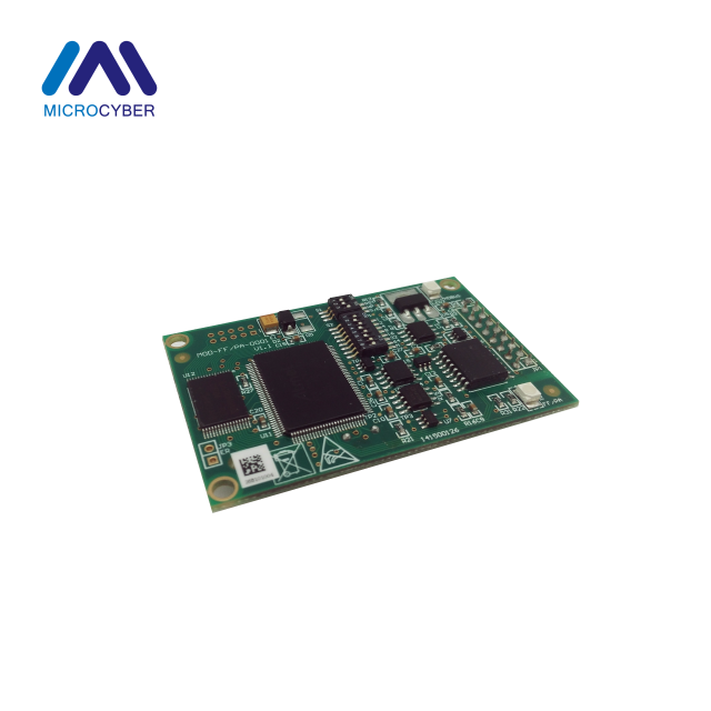
Modbus to HART Module Dimension
HART module PCB depth is 1.6mm, rectangular. Front (shown in Figure 1-4), the highest component is 5mm from board surface; Back, the highest is 9mm from board surface. Others all are surface mount components, lower than 4mm. Length, width, fixed hole‟s location, etc. of HART module are shown in figure below.

Front Dimensions of HART Module

IDC16(2x8) standard socket of 2.54mm spacing is used on backside, to plug into user board; HART module has another 3 fixed holes of Dia.3.0mm, used to fix HART module onto user board.
How To Choose M0310 Modbus to HART Module?

FAQ
Q: Can you introduce Configuration Tool?
A: As previously mentioned, Microcyber can provide PC configuration software for HART module configuration, know more about it please contact us.
Q: Can I get a free electronic manual?
A: Yes, if you want it, please contact us.
Q: Can you provided OEM service?
A: Yes, we can, such as communication board, we can also provided fieldbus development toolkit.