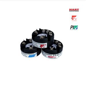
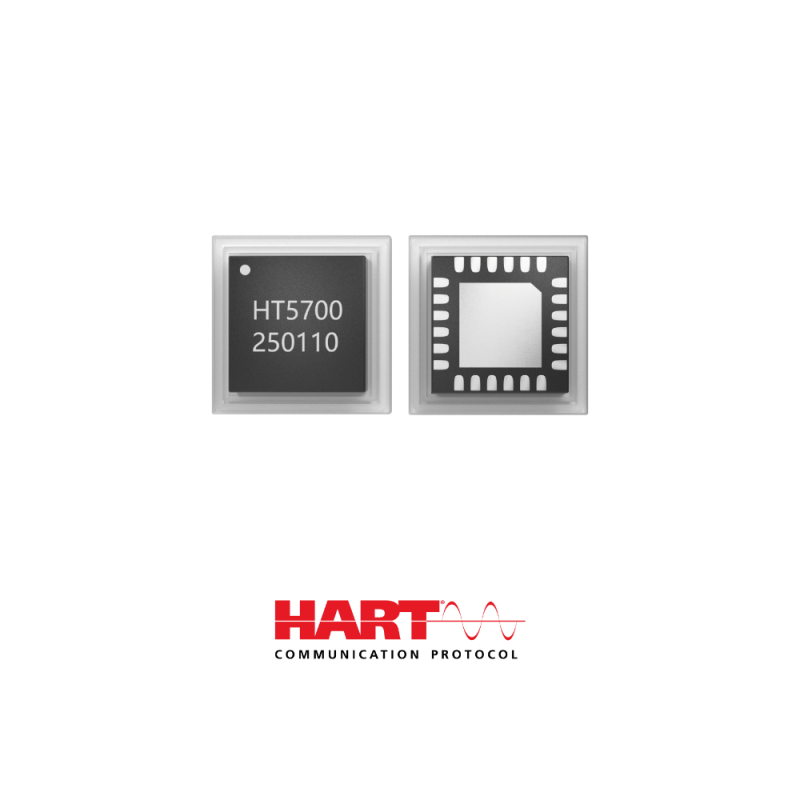
HT5700 Low Power HART Chip (Modem)

- : Microcyber
- : Liaoning, China
- : In Stock
- :10000Pieces/Month
HT5700 Low Power HART Chip (Modem):
1. HT5700 Low Power HART Chip Fully integrated FSK modem compliant with HART standards;
2. HT5700 Low Power HART Chip HART output with drive capability
3. HT5700 Low Power HART Chip Internal integrated crystal oscillator to simplify circuit
4. HT5700 Low Power HART Chip Working temperature: -40℃~+125℃
5. HT5700 Low Power HART Chip Working current: <115u4 (3.3V)
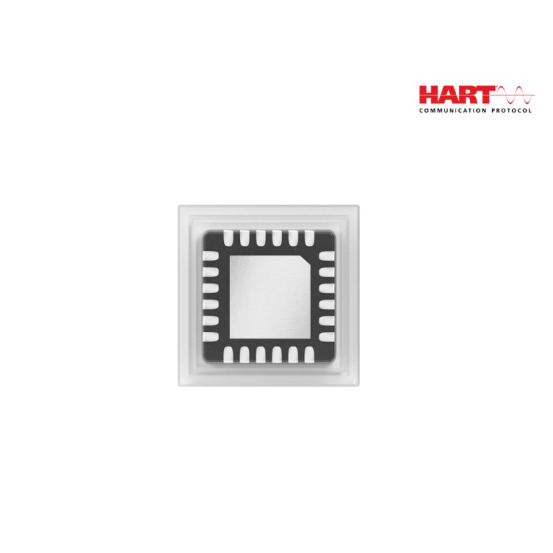
6. HT5700 Low Power HART Chip Dimension: 4mmx4mm, encapsulation: LFCSP24
7. HT5700 Low Power HART Chip Fully compatible with Onsemi AD5700, reducing material costs
HT5700M Low Power HART Chip (Modem): is a single-chip HART communication solution designed for HART® FSK half-duplex modems and complies with the HART physical layer specification. The HT5700 integrates the necessary filtering, signal detection, modulation, demodulation, and signal generation functions, requiring minimal external components. The chip also features an integrated 0.5% accuracy oscillator, significantly reducing board space and making it an ideal choice for HART circuit designs.

Function Block Diagram
HT5700M Low Power HART Chip (Modem) Features:
1. HART-compliant fully integrated FSK modem
2. 115μA maximum supply current in receive mode
3. Suitable for intrinsically safe applications
4. Integrated receive band-pass filter-Minimal external components required
5. Clocking optimized for various system configurations-Ultralow power crystal oscillator (60μA maximum), external CMOS clock source, precision internal oscillator
6. Buffered HART output—extra drive capability
7. 8kV HBM ESD rating
8. 2.7V to 5.5V power supply
9. 1.71V to 5.5V interface
10. -40°C to +125°C operation
11. 4mm × 4mm QFN package
12. HART physical layer compliant
13. UART interface
HT5700M Low Power HART Chip (Modem) Applications:
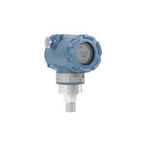
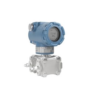
1. Field transmitters
2. HART multiplexers
3. PLC and DCS analog I/O modules
4. HART network connectivity
HT5700M Low Power HART Chip (Modem) Dimension:

HT5700M Low Power HART Chip (Modem) Specifications:
Parameter ① | Min | Typ | Max | Unit | Test Conditions/Comments |
POWER REQUIREMENTS ② | |||||
VCC | 2.7 | 5.5 | V | ||
IOVCC | 1.71 | 5.5 | V | ||
VCC and IOVCC Current Consumption | |||||
Demodulator | 86 | 115 | µA | External clock, −40°C to +85°C | |
179 | µA | External clock, −40°C to +125°C | |||
69 | 97 | µA | External clock, −40°C to +85°C, External reference | ||
157 | µA | External clock, −40°C to +125 °C, External reference | |||
Modulator | 124 | 140 | µA | External clock, −40°C to +85°C | |
193 | µA | External clock, −40°C to +125°C | |||
73 | 96 | µA | External clock, −40°C to +85°C, External reference | ||
153 | µA | External clock, −40°C to +125°C, External reference | |||
Crystal Oscillator ③ | 33 | 60 | µA | External crystal, 16 pF at XTAL1 and XTAL2 | |
44 | 71 | µA | External crystal, 36 pF at XTAL1 and XTAL2 | ||
Internal Oscillator ④ | 87 | 110 | µA | External crystal not required | |
Power -Down Mode | RESET=REF_EN= DGND | ||||
30 | 45 | µA | Internal reference disabled, −40°C to +85°C | ||
55 | µA | Internal reference disabled, −40°C to +125°C | |||
INTERNAL VOLTAGE REFERENCE | |||||
Internal Reference Voltage | 1.49 | 1.5 | 1.51 | V | REF_EN= IOVCC to enable use of internal reference; VCC= 2.7V minimum |
Load Regulation | 18 | ppm/µA | Tested with 50 µA load | ||
OPTIONAL EXTERNAL VOLTAGE | |||||
REFERENCE | |||||
External Reference Input Voltage | 2.47 | 2.5 | 2.53 | V | REF_EN= DGND to enable use of external reference, VCC = 2.7V minimum |
External Reference Input Current | |||||
Demodulator | 14 | 16 | µA | Current required by external reference in receive mode | |
Modulator | 37 | 40 | µA | Current required by external reference in transmit mode | |
Internal Oscillator | 14 | 16 | µA | Current required by external reference if using internal oscillator | |
Power -Down | 14 | 16 | µA | ||
DIGITAL INPUTS | |||||
VIH,Input High Voltage | 0.7× IOVCC | V | |||
VIL,Input Low Voltage | 0.3×OVCC | V | |||
Input Current | −0.1 | +0.1 | µA | ||
Input Capacitance ⑤ | 5 | pF | Per pin | ||
DIGITAL OUTPUTS | |||||
VOH,Output High Voltage | IOVCC−0.5 | V | |||
VOL,Output Low Voltage | 0.4 | V | |||
CD Assert ⑥ | 85 | 100 | 110 | mVp-p | |
HART_IN INPUT ⑤ | |||||
Input Voltage range | 0 | REF | V | External reference source | |
0 | 1.5 | V | Internal reference enabled | ||
HART_OUT OUTPUT | |||||
Output Voltage | 459 | 493 | 505 | mVp-p | AC-coupled (2.2µF), measured at HART_OUT pin with 160Ω load (worst-case load) |
Mark Frequency ⑦ | 1200 | Hz | Internal oscillator | ||
Space Frequency ⑦ | 2200 | Hz | Internal oscillator | ||
Frequency Error | −0.5 | +0.5 | % | Internal oscillator, −40°C to +85°C | |
−1 | +1 | % | Internal oscillator, −40°C to +125°C | ||
Phase Continuity Error ⑤ | 0 | Degrees | |||
Maximum Load Current ⑤ | 160 | Ω | Worst-case load is 160Ω, ac-coupled with 2.2µF. for recommended configuration if driving a resistive load | ||
Transmit Impedance | 7 | Ω | RTS low, at the HART_OUT pin | ||
70 | kΩ | RTS high, at the HART_OUT pin | |||
INTERNAL OSCILLATOR | |||||
Frequency | 1.2226 | 1.2288 | 1.2349 | MHz | −40°C to+85°C |
1.2165 | 1.2288 | 1.2411 | MHz | −40°C to+125°C | |
EXTERNAL CLOCK | |||||
External Clock Source Frequency | 3.6496 | 3.6864 | 3.7232 | MHz |
① Temperature range: −40°C to +125°C; typical at 25°C.
② Current consumption specifications are based on mean current values.
③ The demodulator and modulator currents are specified using an external clock. If using an external crystal oscillator, the crystal oscillator current specification must be added to the corresponding VCC and IOVCC demodulator/modulator current specification to obtain the total supply current required in this mode.
④ The demodulator and modulator currents are specified using an external clock. If using the internal oscillator, the internal oscillator current specification must be added to the corresponding VCC and IOVCC demodulator/modulator current specification to obtain the total supply current required in this mode.
⑤ Guaranteed by design and characterization, but not production tested.
⑥ Specification set assuming a sinusoidal input signal containing preamble characters at the input and an ideal external filter (see Figure 18).
⑦ If the internal oscillator is not used, frequency accuracy is dependent on the accuracy of the crystal or clock source used.
HT5700M Low Power HART Chip (Modem) Typical Connection Diagram for External and Internal Filter Options:

HT5700 Typical Connection Diagram for External and Internal Filter Options