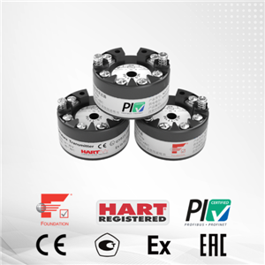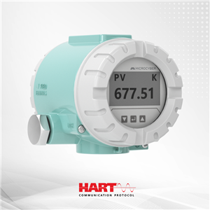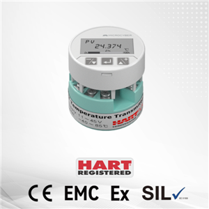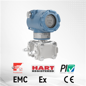
NCS-TT305 HART temperature transmitter
NCS-TT305 series HART temperature transmitter
The NCS-TT305 series HART temperature transmitter is a high-precision, low-temperature-drift, and high-reliability product, an indispensable field device in process control. This device integrates a rich set of functional modules, enabling both general detection functions and complex control strategies.
The NCS-TT305 utilizes digital technology, is compatible with various RTD and thermocouple sensors, has a wide measuring range, a simple interface between the field and control room, and significantly reduces installation, operation, and maintenance costs.
The NCS-TT305 series temperature transmitter supports 4-20mA+HART protocol and LCD display, and can be widely used in industries such as petroleum, chemical, power, and metallurgy.
NCS-TT305 series HART temperature transmitter Features:
· Dual-chamber design, corrosion-resistant low-copper aluminum alloy housing, copper content less than 0.2%
· LCD display and button parameter configuration
· Electromagnetic compatibility (EMC) complies with IEC61326 standard
· Provide EDD, FDI, and DTM files to facilitate system integration
· HART 7.9 standard and BURST mode
· Low temperature drift PT100 ±0.003℃/℃
· The accuracy level less than 0.1, and the measurement accuracy of PT100 is less than ±0.1℃
· Sensor drift detection to improve data reliability
· Multiple international certifications, working safely in explosion-proof hazardous areas
· Working in ultra-low temperature environment of -55℃
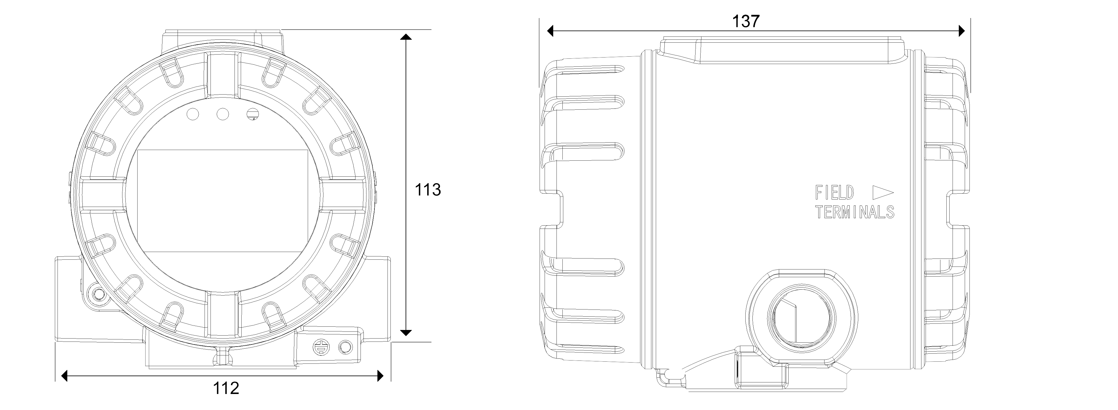
NCS-TT305 Series HART Temperature Transmitter size shown:
NCS-TT305 Series HART Temperature Transmitter wiring diagram:
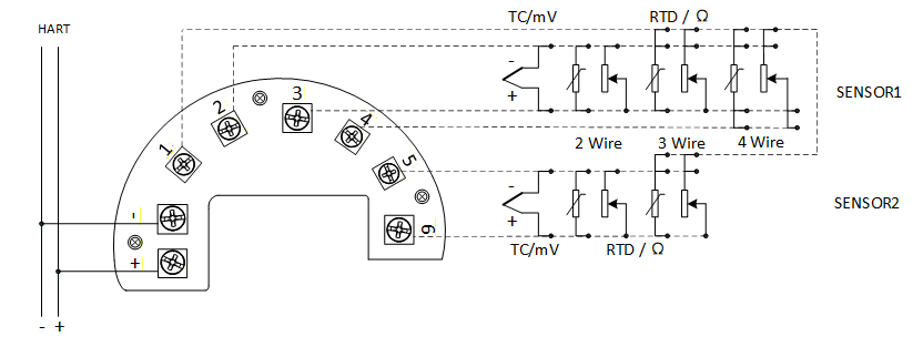
Note: When the sensor type for Channel 1 is set to 0~40000R two-wire, the wiring is 1 and 3; when the sensor type for Channel 2 is set to 0~40000R two-wire, the wiring is 1 and 6.
The power supply and bus signal of the temperature transmitter share a single cable, called the bus cable. It is recommended to use the fieldbus-specific cable recommended by IEC61158-2. Signal cables and bus cables should not share conduits or exposed cable trays with the power lines of other devices, and should be kept away from high-power equipment. The shielding wires at both ends of the bus should be grounded using a single-ended grounding method.If the sensor cable length is not less than 30 m, shielded cable must be used and grounded at both ends. Shielded cable is generally recommended.
Remark: The DIP switch on the back of the LCD display is reserved and has no actual function.
When used in intrinsically safe (IS) hazardous areas, the “+” and “-” power terminals shall be connected to an IS barrier.