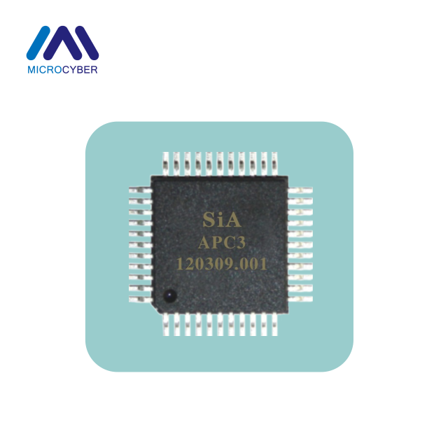
HT1200M Hart Modem Typical


- : Microcyber
- : Liaoning, China
- : In Stock
- : 500 Sets/Month
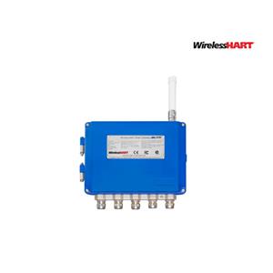
The HT1200M is a single-chip, CMOS modem for use in Highway Addressable Remote Transducer (HART) field instruments and masters. The modem and a few external passive components provide all of the functions needed to satisfy HART physical layer requirements including modulation, demodulation, receive filtering, carrier detect and transmit-signal shaping.
HT1200M Hart Modem Typical General Description
The HT1200M is a single-chip, CMOS modem for use in Highway Addressable Remote Transducer (HART) field instruments and masters. The modem and a few external passive components provide all of the functions needed to satisfy HART physical layer requirements including modulation, demodulation, receive filtering, carrier detect and transmit-signal shaping. The HT1200M is pin-compatible with the SYM20C15. See the Pin Description and Functional Description sections for details on pin compatibility with the SYM20C15.
The HT1200M uses Phase Continuous Frequency Shift Keying (FSK) at 1200 bits per second. To conserve power the receive circuits are disabled during transmit operations and vice versa. This provides the half-duplex operation used in HART communications.
Features
Can be used in designs presently using the SYM20C15 or equivalent type chip
Single-chip, half-duplex 1200 bits per second FSK modem
Bell 202 shift frequencies of 1200 Hz and 2200 Hz
3.3V-5.0V power supply
Transmit-signal wave shaping
Receive band-pass filter
Low power: optimal for intrinsically safe applications CMOS compatible
Internal oscillator requires 460.8kHz crystal or ceramic resonator
Meets HART physical layer requirements
Industrial temperature range of -40 °C to +85 °C
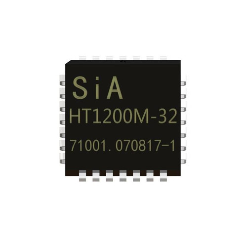
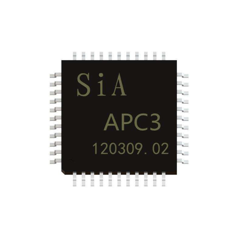
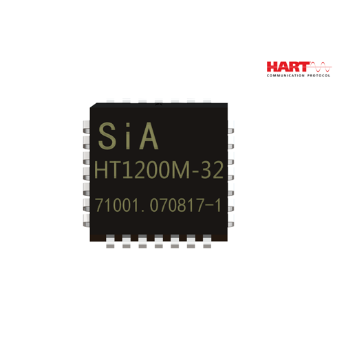
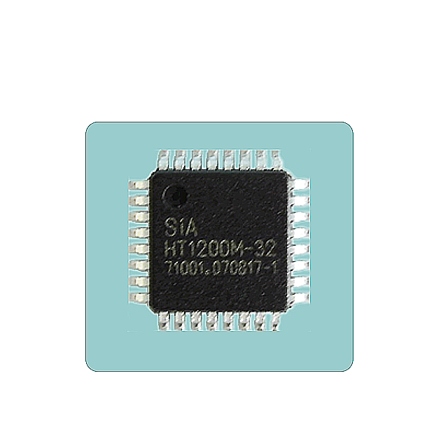
Available in a 28-pin PLCC and 32-pin LQFP packages
Typical Application

Table 1 HT1200M Pin Descriptions | ||||
Signal | Type | PLCC | LQFP | Description |
TEST1 | input | 1 | 28 | Connect to Vss. |
TEST2 | — | 2 | 29 | No connect. |
TEST3 | — | 3 | 31 | No connect. |
TEST4 | — | 4 | 32 | No connect. |
TEST5 | input | 5 | 1 | Connect to Vss. |
INRESET | input | 6 | 2 | Reset all digital logic when low |
TEST7 | input | 7 | 3 | Connect to Vss. |
TEST8 | input | 8 | 4 | Connect to Vss. |
TEST9 | input | 9 | 5 | Connect to Vss. |
OTXA | output | 10 | 7 | Modulated output transmit and transmit signal to 4-20mA loop. FSK modulated HART interface circuit. |
IAREF | input | 11 | 8 | Analog reference voltage. |
ICDREF | input | 12 | 9 | Carrier detect reference voltage. |
OCBIAS | output | 13 | 10 | Comparator bias current. |
TEST10 | input | 14 | 11 | Connect to Vss. |
VDDA | power | 15 | 13 | Analog supply voltage. |
IRXA | input | 16 | 14 | FSK modulated HART receive signal from 4-20mA loop interface circuit |
ORXAF | output | 17 | 15 | Analog receiver filter input. |
IRXAC | input | 18 | 16 | Analog receive comparator input. |
OXTL | output | 19 | 17 | Crystal oscillator output. |
IXTL | input | 20 | 18 | Crystal oscillator input. |
VSS | ground | 21 | 6,20 | Ground. |
VDD | power | 22 | 21,30 | Digital supply voltage. |
INRTS | input | 23 | 22 | Request to send. |
ITXD | input | 24 | 23 | Input transmit data. Transmitted HART data stream from UART. |
TEST11 | — | 25 | 24 | No connect. |
ORXD | output | 26 | 25 | Received demodulated HART data to UART. |
OCD | output | 27 | 26 | Carrier detect output. |
TEST12 | — | 28 | 27 | No connect. |
VSSA | ground | — | 12,19 | Analog ground |
Function Description
The HT1200M is a functional equivalent of the SYM20C15 HART Modem. It contains a transmit data modulator and signal shaper, carrier detect circuitry, analog receiver and demodulator circuitry and an oscillator, as shown in Figure 4.
The internal HART modulates the transmit-signal and demodulates the receive signal. The transmit-signal shaper enables the HT1200M to transmit a HART compliant signal. The carrier is detected by comparing the receiver filter output with the difference between two external voltage references. The analog receive circuitry band-pass filters the received signal for input to the modem and the carrier detect circuitry. The oscillator provides the modem with a stable time base using either a simple external resonator or an external clock source.

Characteristics
ABSOLUTE MAXIMUMS | ||||
Symbol | Parameter | Min. | Max. | Units |
TA | Ambient | -40 | +85 | ℃ |
TS | Storage Temperature | -55 | +150 | ℃ |
VDD | Supply Voltage | 2.7 | 5.5 | V |
VIN , VOUT | DC Input, Output | -0.3 | VDD+0.3 | V |
TL | Lead Temperature (soldering) | 250 | ℃ | |
DC CHARACTERISTICS (VDD = 2.7V to 5.5V, VSS = 0V, TA = -40C to +85C) | ||||||
Symbol | Parameter | VDD | Min. | Typical | Max. | Units |
VIL | Input Voltage, Low | 2.7-5.5V | 0.3*VDD | V | ||
VIL | INRESET、INRTS | 2.7-3.3V | 0.9 | 1.2 | 1.4 | V |
VIH | Input Voltage | 2.7-5.5V | 0.7*VDD | V | ||
VIH | INRESET、INRTS | 2.7-3.3V | 1.3 | 1.8 | 2.3 | V |
VOL | Output Voltage, Low (IOL = -1.8mA) |
2.7-3.3V |
0.4 | V | ||
VOH | Output Voltage, High (IOH = -1.8mA) |
2.7-3.3V |
VDD-1.0 | V | ||
CIN | Input Capacitance Analog Input IRXA Digital Input | 2.1 20.8 3.1 | pF | |||
IIL/IH | Input Leakage Current | ±5 | µA | |||
IOLL | Output Leakage Current | ±5 | µA | |||
IDD | Power Supply Current (RBIAS=500kΩ,IAREF=1.235V) | 3.3 5.0 | 170 200 | µA | ||
IAREF | Analog Reference | 3.3 5.0 | 1.2 | 1.235 2.5 | 2.6 | V |
ICDREF | Carrier Detect Reference (IAREF=.08V) | 1.15 | V | |||
OCBIAS | Comparator Bias Current (RBIAS=500kΩ, IAREF=1.235V) | 2.5 | µA | |||