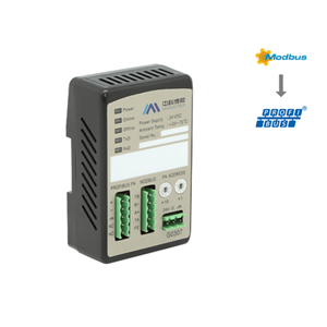
G0313 MODBUS RTU to FF DIN Rail Mounting Gateway
G0313 Modbus to FF Gateway is a gateway device of Modbus protocol and FF protocol developed by Microcyber. As Modbus master station, G0313 Modbus to FF Gateway communicates with Modbus-RTU device via RS485 interface, and it can convert the data of Modbus-RTU device to FF device variable output. G0313 Modbus to FF Gateway is shown in Figure 1:

Outer Size Diagram

Figure 2 Outer Size of Gateway Device (Unit: mm)
Configuration of DIP Switch
There is a 3-bit DIP switch for G0313 Modbus to FF Gateway, shown as Figure 5.
SIM: Simulation switch, used for “simulation function”.
WP: Write protection, all the write operation for FF smart pressure transmitter shall be refused, which avoid data modification at random.
RST: Reset, reset device date to factory original. Power off the device at first, and m ade the switch at ON, and then power on the device, the device shall be reset to factory original.

Introduction for Function
Default configuration of Modbus to FF Gateway has 1 RES function block, 4 for each AI, AO, DI, DO, PID function block and Modbus transducer block (Modbus_TB ) complying to FF specifications. AI, AO, DI, DO respectively supports 8 channels (CHANNEL ), each channel is corresponding to analog/discrete input and output parameters of Modbus transducer block.
Function Block name | Description |
Resource (RES) | Resource block is used to describe the device identity in the field, such as device name, manufacture, serial number. There is no input or output parameter in the resource block. Generally, there is only one resource block for each device. |
Modbus_TB (MTB) | Configure Modbus communication parameters via transducer block, such as baud rate, stop bit, communication overtime, etc., Modbus communication configuration parameter. |
Analog Input (AI) | Analog input function block is used to achieve transducer block input data and transfer to other function blocks, has the function of range conversion, square root, cut mantissa, etc. |
Analog Output (AO) | Analog output function block is used to transfer output data to transducer block, then to operate physical device. |
Discrete Input (DI) | Discrete input function block, achieve transducer block input data and transfer to other functions blocks. |
Discrete Output (DO) | Discrete output function block is used to transfer discrete output data to transducer block, then to operate physical device. |
Proportional Integral Derivative(PID) | PID function block has the function of PID control and setting point adjustment, process value(PV) filtering and alarm, output tracking, etc. |
4.1 Communication Parameter for Modbus Transducer Block
The user is able to configure the Modbus communication parameter, such as baud rate, stop bit, communication timeout, etc. The Modbus communication configuration parameters are shown as following:
Parameter Name |
Data Type |
Function Description |
MEDIA |
USIGN8 | Physical transmission medium, 0:RS232,1:RS485 |
BAUD_RATE |
USIGN8 | Baud rate,0:9600(default),1:19200,2:15625,3:31250,4:62500,5:125000 |
STOP_BIT |
USIGN8 | Stop bit,0:one stop bit,1:two stop bits |
PARITY |
USIGN8 | Calibration bit,0:no calibration bit,1:even calibration,2:odd calibration |
CRC_ORDER |
USIGN8 | CRC calibration byte order,0:high byte first,1:low byte first |
TIME_OUT |
USIGN16 | After sending MODBUS request, the maximum time waiting for slave station response. The unit is ms, default 300ms. |
NUMBER_OF_RETRY |
USIGN8 | When the waiting response is timeout, the number for resending the request. The range is 0-255. |
SLAVE_ADDRESS |
USIGN8 |
Address for MODBUS slave station. The range is 0-255. |