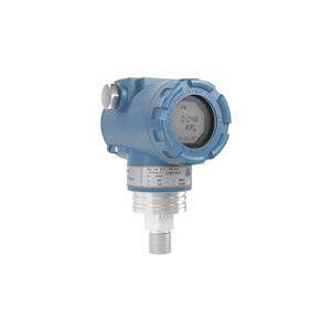
Development of hart pressure transmitter using domestic hart chip HART1200M
The HART protocol has an important place in the design of sensor transmitters. To summarize, simple transmitter designs traditionally pass an analog value, often called a process variable (PV), through a current loop. This PV is typically associated with a sensor value (humidity, temperature, pH, pressure) that is represented by a 4 to 20 mA analog signal. The analog value can travel over kilometers of wire to reach the analog front-end circuitry, which records the potential drop across the shunt resistor as it interprets the transmitted sensor value.
Now, this is great if you want to communicate a value through lengthy wiring. But what if you want to send or receive additional data over the same two wires? By including HART in the transmitter design.
By including a HART modem, your transmitter design can now communicate a wide range of calibration routines, send diagnostic data, or communicate PVs from other sensor platforms.This communication can be accomplished through the HART frequency shift keying (FSK) waveform, which is coupled to an analog current signal.
Before diving into the details of two-wire HART transmitter design, take a crash course (or refresher course) on simple two-wire transmitter design. Have you completed the refresher yet? Amazingly you are halfway there.
Let's start with the circuit shown in Figure 1.

This circuit may look a little daunting, but the only difference between this circuit and the one shown in the Simple Two-Wire Transmitter Design blog post is the inclusion of the DAC8740H HART modem.The low quiescent current of the DAC8740H HART modem is 180µA, which makes this modem an excellent candidate for a low-power sensor-transmitter solution. The gain in loop current (1+R3/R4) will be determined using the method shown in the collision procedure.
There are only two connections between the HART modem and the transmitter, as shown in Figure 2.The DAC8740H MODOUT pin of the HART modem is connected to the transmitter through an AC coupling capacitor, C1. This capacitor, along with R6, creates a high-pass filter that attenuates frequencies below the selected cutoff frequency of 1/(2 x π x R6 x C1).
During operation, the HART FSK signal is driven by MODOUT and superimposed on the analog value of the loop current with an FSK amplitude of 1mApp. Resistor R6 changes and sets the FSK amplitude which is connected in series from the HART modem to the non-inverting terminal of U3. By superposition, Equation 1 calculates the AC component of the current loop as:
Equation 1:
Thus, R6 = (VHART/IIOUT p-p) (1 + R3/R4).
Substituting the schematic values of R3, R4 and the peak-to-peak voltage of MODOUT will reveal the value of R6. Once the value of R6 is obtained, C1 can be calculated by selecting the cutoff frequency of the high-pass filter.In a high-precision, loop-powered, 4mA to 20mA field transmitter with a HART modem reference design, a cutoff frequency of 679Hz ensures that noise and frequencies below 1200Hz and 2200Hz are efficiently attenuated without significantly affecting the HART band frequency Range.
The HART signal receive pin - the DAC8740H MOD_IN pin - is connected to the positive bus power network of the transmitter circuitry via AC coupling capacitor C2 and into the internal bandpass filter.
The next step is to create a smart sensor-transmitter solution by choosing a sensor interface like the TMP116, which offers better accuracy than a Class a resistance temperature detector (RTD) from a single chip.